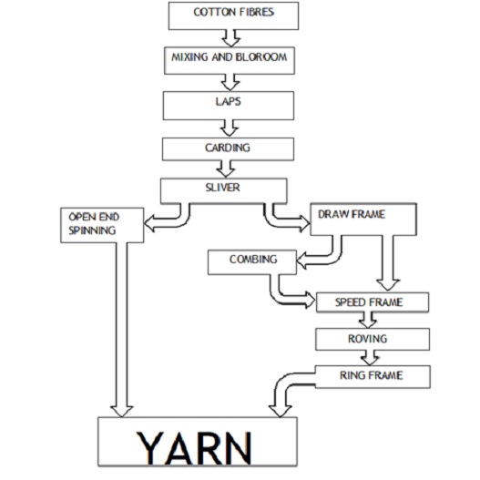
An ideal line for processing short-staple cotton
An ideal line for processing cotton or Erection for the new blow room line basic setting is
1- Bale opening and mixing
Blendomate/unifloc/autoplucker
2- Coarse opening and cleaning
Uniclean/ maxi flow/CLP
3- Fibre mixing
MXI/MPM/unimix (8-chamber multimixer)
4- Fine opening/Cleaning
Uniflex/CLC3/CLU
5- Contamination sorting
Jossi magic eye 2/Sp-FPU/TS-T5/loptex opto-sonic
6- Dedusting
Condensor/dust-ex
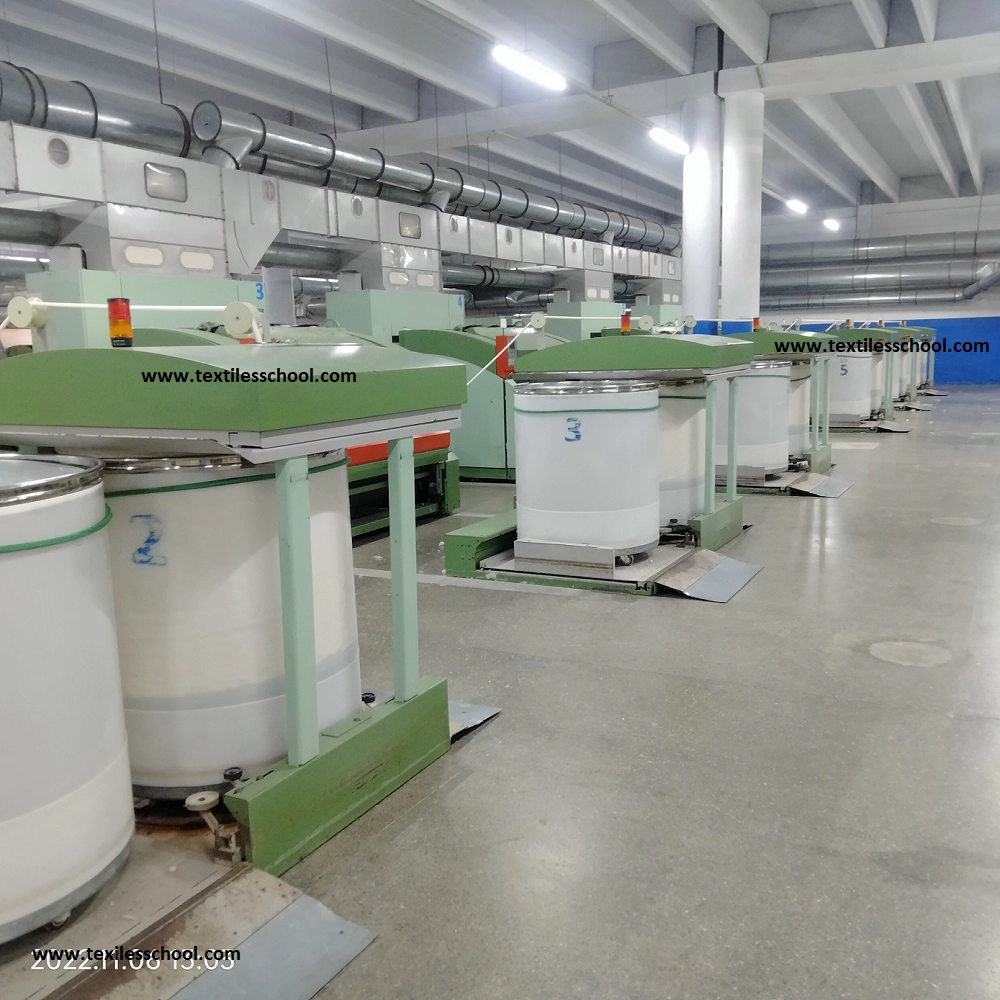
7- Carding
Reiter C-70,C-60/trutzschler TC15, TC11
- These are essential for an ideal cotton fibre opening and cleaning
- Metal fire detection is vital to prevent hazards and machinery damage.
Essential for fibre opening cleaning and mixing
- Bale opening and homogenous mixing
- Coarse opening
- Fibre mixing
- Fibre opening
- Contamination sorters
- Dedusting
- Carding
These steps are essential for the proper opening of any type of cotton Pima Giza, Turkmen, Tajik, Sadani, Chad, Mali, Ivory Coast, Australian, USA, Brazillian, Shanker, MCU5, DCH32 Spanish and Pakistani. all these steps must be followed. Beaters types speed etc may vary but sequencing should be always there.
Unifloc A-11
- Production Level =15
- 2.7-1.5-2.7-1.5mm
- Beater rpm =1600O(468 pins on the beater)
- Traversing speed 8.0 m/min
- Penetration depth 1.5mm/reverse
- lifting speed 25.3 mm/sec
- Air Vaccum-400~-480 Pa
- Material fan speed =1420×190/140= 1925rpm
- Pressure before fan -1100 Pa
- Pressure for dust extraction -600 Pa
- maximum bale width = 2.0m and height = 1.6 m
Uniclean B-11
- Cleaning intensity 0.8
- Relative waste amount 5
- Beater speed 835 rpm
- Grid angle 9.8
- Cylinder position 66mm
- Inlet pressure 200 Pa
- Outlet pressure 130 Pa
- Dust vacuum -800Pa
- Waste Vacuum -2300 Pa
Unimix B-70
- Pressure set to stop A-11 300Pa
- Setting to start feeding 200 Pa
- Outlet pressure for B-60 100 Pa
- Cleaning roller to feed 3 (0~6) roller setting
- Gridbar setting 3 (0~5)
- Stripping plate 25
- Evener roller setting 15mm
- Stripping roller setting 5mm
- Spiked lattice geared motor 5.0
- Feed roller geared motor 4.2
- Approximate speeds
- Spike lattice= motor(57~280) X 104/184 = 24.87~122.17 (95 rpm)
- Stripper roll =1380 x 94/144 =900 rpm
- Opening roll 1420 x 94/144 =800 rpm
- Take off roll =1380 x 79/194 =560 rpm
- Pressure in storage suction 0~50 Pa
Uniflex B-60
- Production step 15
- Feed roll rpm 6
- Cleaning intensity 0.2
- Beater speed 552 RPM
- Relative waste amount 5
- Grid angle 45mm
- Commercial staple 30.1mm
- Outlet pressure -200 Pa
- Dust vacuum -200 Pa
- Waste vacuum -1800Pa
Blow room fibre growth report
Fibro graph report
| Description | UHML | SFI | UNF |
| Bales | 31.58 | 8.35 | 82.26 |
| Plucker | 31.81 | 8.56 | 81.93 |
| Auto plucker | 32.11 | 8.43 | 81.90 |
| Maxi-flow | 32.55 | 8.86 | 81.00 |
| MPM | 31.34 | 9.3 | 80.80 |
| CVT1 | 31.28 | 10.20 | 80.6 |
| CXL3 | 31.13 | 8.8 | 80.5 |
| Chute | 31.83 | 9.5 | 80.5 |
Blow room fibre growth AFIS Pima cotton
| Description | UQL” | SFC% | IFC% | Mat ratio | Neps ct/gm |
| Mixing | 1.45 | 14.6 | 3.2 | 1.00 | 92 |
| B0 | 1.39 | 14.4 | 3.3 | 1.00 | 96 |
| B11 | 1.39 | 16.1 | 3.6 | 0.98 | 124 |
| MPM | 1.39 | 15.9 | 3.6 | 0.99 | 130 |
| B-60 I | 1.38 | 17.5 | 4.3 | 0.97 | 204 |
| B-60 II | 1.40 | 20.0 | 5.0 | 0.95 | 208 |
| SME-1 | 1.39 | 18.8 | 4.1 | 0.96 | 213 |
| SME-2 | 1.41 | 18.9 | 4.5 | 0.96 | 237 |
| SME-3 | 1.40 | 20.1 | 5.0 | 0.95 | 214 |
| SME-4 | 1.41 | 20.6 | 4.9 | 0.94 | 223 |
Blow room Checkpoint
- Consumption of bales
- Blend consistency
- Mixing conditions
- Tuft-size feed to the breaker
- Cutting of stock by tenter
- Condition of feed lattice and spike lattice etc.
- The setting of the evener roller and spike lattice
- Magnets cleaning
- Condition of grid bars
- Condition of beaters at overhauling
- Lap conditions
- Inspection of trash chambers to check the richness of lint in waste.
- Working on piano motion
- Condition of condensers at overhauling
- Material level in reserve tank and feeding trunk and signal of start and stop feeding.
- Feed at card
- Balance of air currents (one week)
- Lap shape, splitting licking, selvedge etc.
- Cutting and doffing of the lap, the width of the lap
- Lap weight and meters calibration.
- Lap rejection percentage
- Stoppages and reasons
- Contamination picking monitoring at different stages in the blow room
- The lap width should be 5 cm less than the card width to prevent side blowing of fibres
- Lap handling and colour of lap rod at each scutcher
- General overhauling of the machine.
Card C-51
- Feed through setting 16mm
- Chute pressure setting 400~500 Pa
- Plate setting fully opened
- Delivery speed 118m/min
- Production 30 kg/hr
- Grain/yd 60
- Sliver weight 18 kg(4230m)
- Cylinder speed 400 rpm
- Flats speed is 0.19 m/min
- Total draft 124
- Sliver weight of batt 525 gram/m
Carding fibre growth (AFIS ) Pima cotton
| Card # | Nep ct/ gm | Nep removal % |
| 13 | 42 | 81.05 |
| 14 | 56 | 74.74 |
| 15 | 42 | 81.05 |
| 16 | 48 | 78.35 |
| 17 | 41 | 81.51 |
| 18 | 39 | 82.41 |
| 19 | 43 | 80.60 |
| 20 | 55 | 75.19 |
| 21 | 42 | 81.05 |
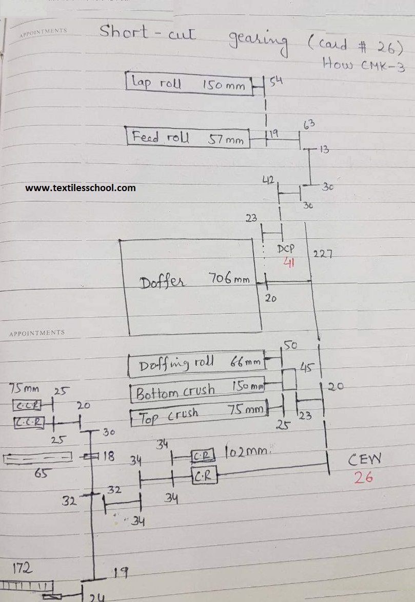
Gearing diagram howa CMK-3
Specification of carding ( carding gauges)
| Description | Gauges | Rough speed |
| Feed roll | 57 mm | 5 rpm |
| Taker-in | 249.5mm | 900 rpm |
| CRC | 99.6mm | 120 rpm |
| Cylinder | 1289mm | 360 rpm |
| Doffer | 706mm | 30 rpm |
| Doffing roll | 66mm | 150 rpm |
| Take off roll | 42mm | 220 rpm |
| Flats | 1 5/16” | 5 inches/min |
| Flate brush | – | 50 rpm |
| Calender roll | 102 mm | 250 rpm |
| C. calender roll | 75 mm | 360 rpm |
| Top crush roll | 75 mm | 300 rpm |
| Bottom crush roll | 150 mm | 165 rpm |
| Trumpet | 11 mm | – |
| Coiler trumpet | 7 mm | – |
Calculation from gearing
Cylinder speed
= 960 x 171.5/457 =360 rpm
=360 x 1289 x π /1000
= 1457.8 m/min
Taker-in speed
= 360 x 457/178 = 924 rpm
= 924 x π x 249.5/1000
=724 m/min
Flats speed
= 360 x 102/305 x 1/24 x 2/14 x 14x 36.5/24.5
=5.05 inches/ minutes
Tension draft between lap and feed
D1 = πx57x5.0/(πx150x1.75)
=1.08
Major draft between feed and offer
D2 = π x 706 x 30/(π x 57 x 5)
=74.31
Web tension between doffer and C.C.R
D3 = π x 102 x 250/(π x 706 x30)
= 1.204
The tension between C.R and C.C.R
D4 = π x 75 x 260/(π x 102 x250)
=1.059
Total draft of the machine
D= 1.086 x 74.32 x 1.204 x 1.059
=102.86
Transfer ratio (stripping power)
=Surface speed of cylinder/surface speed of taker-in
= π x 1289 x360 /(π x 249.5 x 900)
= 2.07
Hence, 1:2.07
Carding power
=Surface speed of cylinder in inches/min/linear speed of flat inches/min
=1457.8 x 39.37/5.05
=113654
Condensation power
=surface speed of cylinder/surface speed of doffer
=π x 1289 x 360/π x 705 x30=21.09
Coiling ratio
= RPM of cooler tube/RPM of can
i.e. =1 x 172 x 24 x 18/(2 x 19 x 65) =30
Hence 1:30
False twist
= RPM of coiler tube/ surface speed of C.C. Roll
i.e. = 1 x (250 x 32/34 x 18/65)/(π x 75/1000 x 360)
=0.77
Actual twist
= RPM of can/ surface speed of C.C.R
= (250 x 32/34 x 19/24 x 2/172)/(π x 75/1000 x 360)
=0.026
Carding checkpoint
- Check feeding conditions(patchiness, distribution layers, ragged selvedge etc centrally feeding lap is necessary.
- The lap width is 50mm lower than the card width
- Feed roller grip gauge 0.005” between the feed roller and feed plate through out width of the card.
- Condition of the scavenger rod, the conical build is an indication of an uneven setting between the licker-in and feed roller.
- Condition of licker-in dropping for the richness of lint.
- Condition of wires at the overhauling stage
- Flats cleaning by brush
- The density of flat strip
- Condition of the web. A good web should not have ragged selvedge, holes thick and thin patches or lumps of fibres called snowballs. A cloudy web is a sign of poor carding
- Condition and size of the trumpet
- Inside coiler and can
- Can filling
Stop-motion of the card
- Feed roller (too thick and too thin lap)
- C.C.R (Lapping)
- Doffer ( Lapping)
- Calander roll( low tension in web, lapping)
- Empty lap and empty can
- Sliver breakage C.R and coiler C.R


